Hi Forum Members,
There seem to be as many ESR meter designs as people who use them. I have decided to share my ESR meter design with the group.
Strictly speaking this ESR meter does not measure ESR, it measures the impedance of the capacitor under test at 100kHz. For Capacitors larger than a few uF this is approximately equal to the ESR.
ESR meter do not need to be precise, it most instances a bad capacitor will have any ESR many times that of a good one.
When I was kid, radio manufacturers would sell transistor radios based on the number of transistor in them. This is a 5 transistor ESR meter. The only IC that used is a 5V regulator. The circuit should also work directly from 3 or 4 AA batteries without the regulator. The design should work with any general purpose transistors. The diodes in the meter circuit will effect the meter scale. Use small signal Schottky diodes such as 1N5711, common diodes like BAT54 have too much capacitance. OA91 or similar Ge diode should also work.
10th Anniversary Edition
I shared a modified version the ESR meter in this message:
https://www.eevblog.com/forum/projects/5-transistor-esr-meter-design/msg4608886/#msg4608886
Two additional transistors are used to detect if the resistance of the capacitor being tested is less than 25  All the other features remain the same. The new design was generated in KICAD version 5.00
The maximum voltage on the capacitor under test is 100mV. This allows for in-circuit testing.
The design started with modelling the circuit in LTspice:
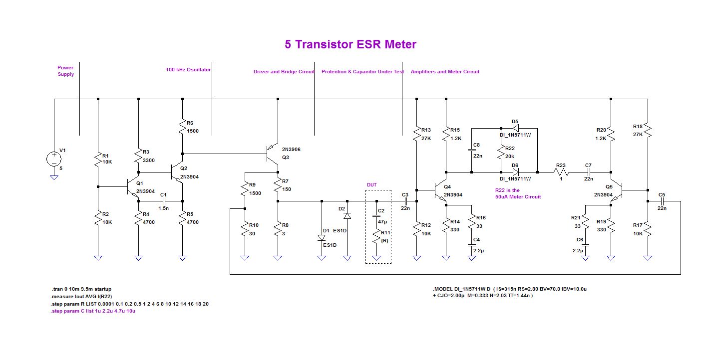
The building blocks are labelled.
This is the result of the LTspice modelling, it shows how the meter deflection changes with ESR.
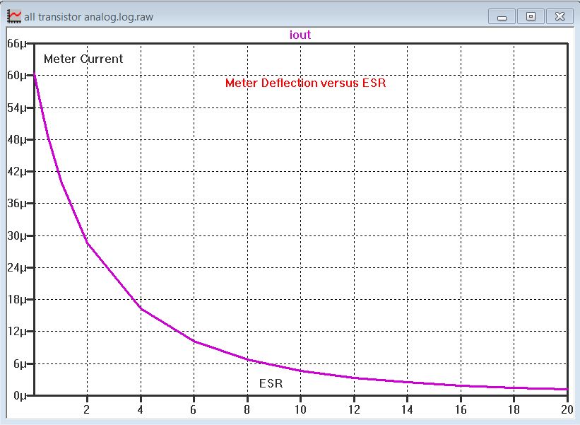
This good because it gives an expanded scale.
From the LTspice model, I made the OrCad schematic:

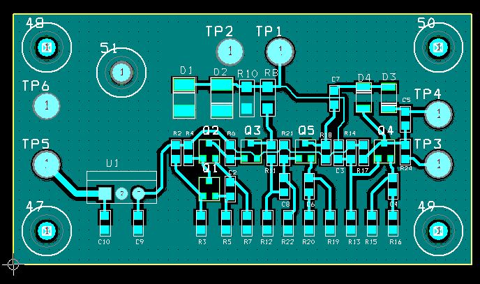
And then the board layout, I used SMD parts, but thru hole parts could also be used.
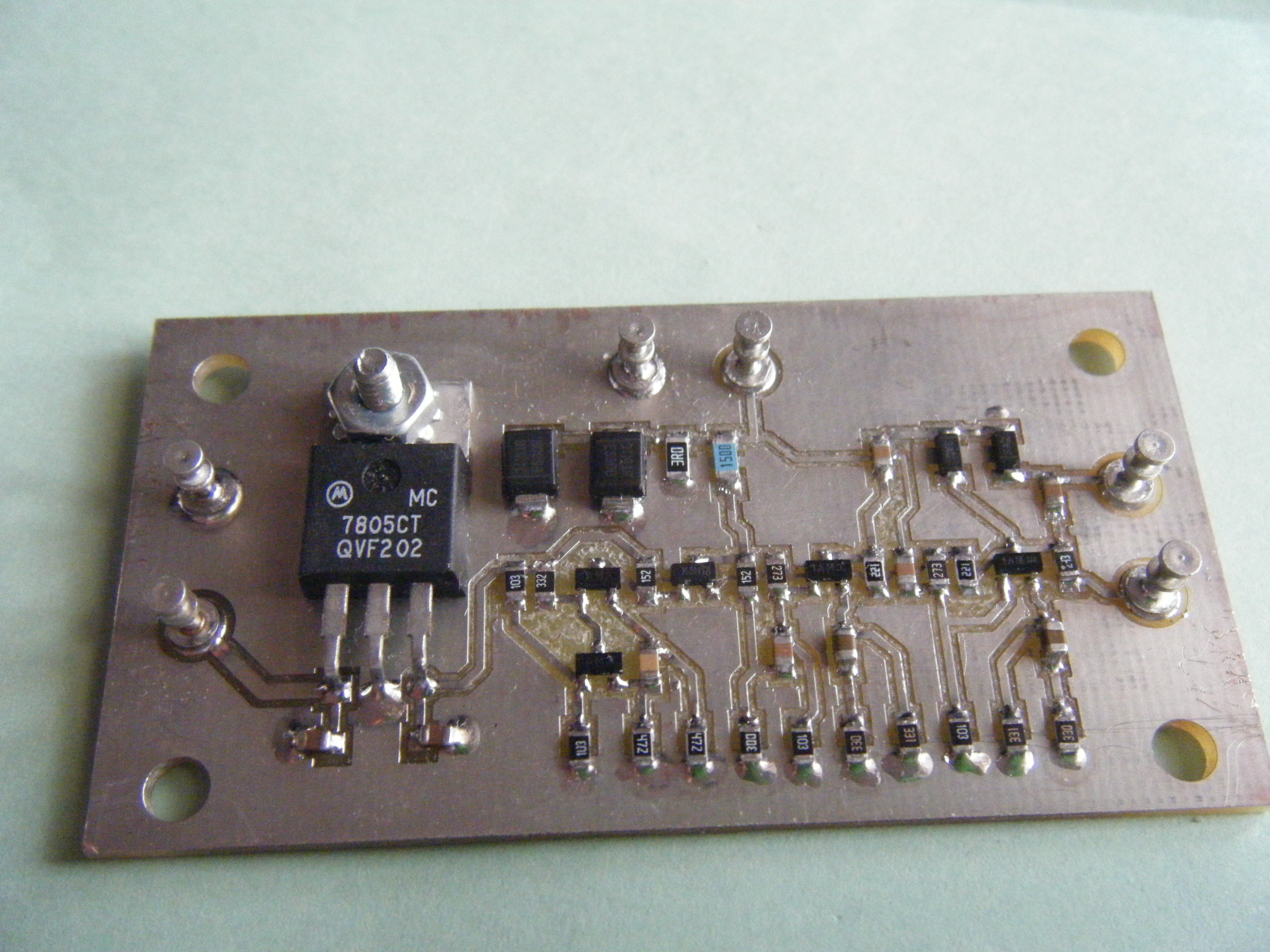
The circuit was made from the above design and the components attached:
The meter circuit was hooked up. The meter deflection was measure using some low value resistor. Artwork for a new meter scale was drawn using Corel Draw. The meter scale was printed on Photo paper to be attached to the meter.

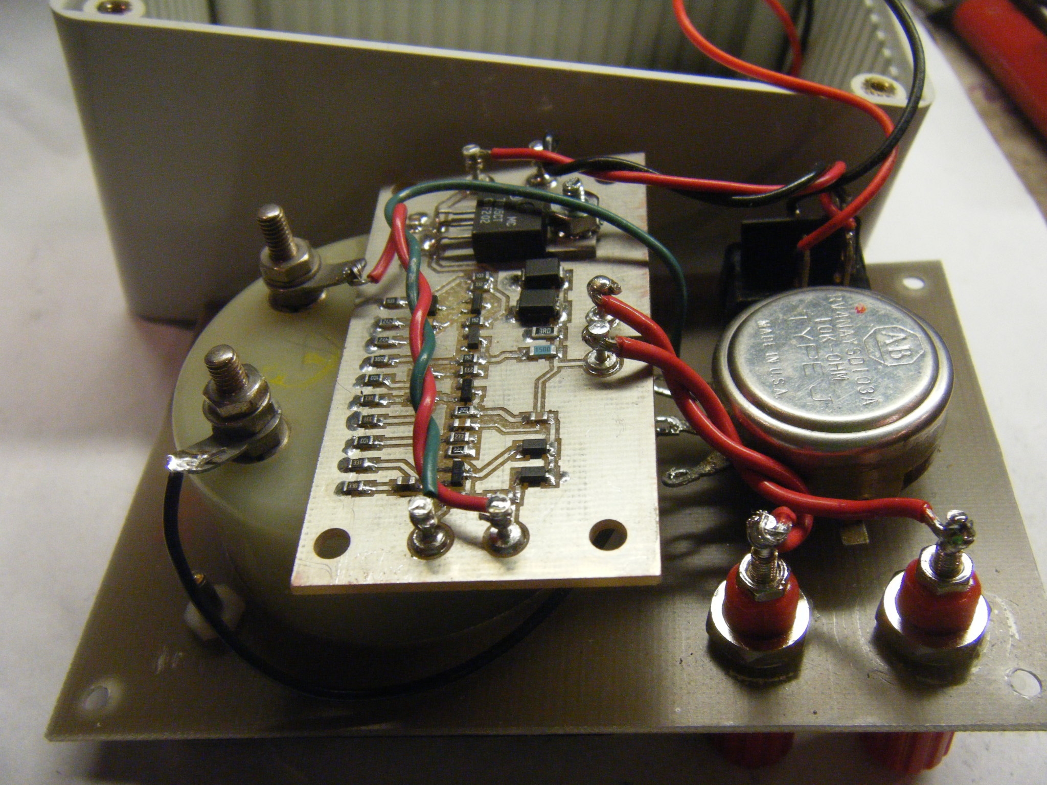
The final assembly was completed. Here is a view of the inside of the ESR meter:
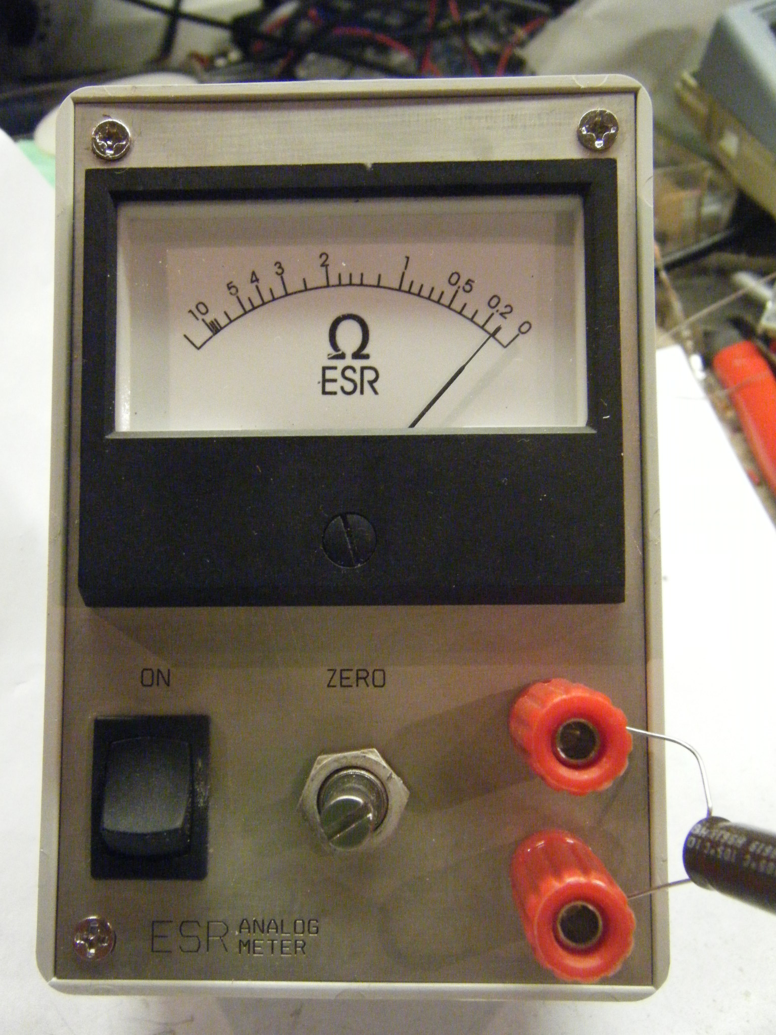
And the Outside:
If you build this, remember to discharge capacitors before using.
Current consumption is 26mA, that is about 25 hours of use.
Regards,
Jay_Diddy_B aka John